
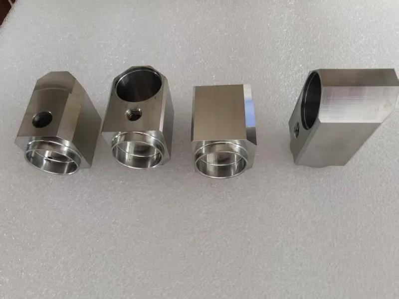
An octagonal sensor housing machined from AISI 316L (1.4404), carrying a Φ20 H8 bore, a Φ19.3 H10 bore, 1/4″-28 UNF 2B and M8×1.25 threads, and weld-zone edges held at R0.05 max. Every machined face is Ra 0.8 and burr-free, and the part is an agency-approved product with full traceability.
| Part | Sensor housing: octagonal body, multi-face machining |
|---|---|
| Material | AISI 316L (1.4404) austenitic stainless steel |
| Bores | Φ20 H8 (+0.033) · Φ19.3 H10 |
| Threads | 1/4″-28 UNF 2B · M8×1.25, chamfered to the root of the first thread |
| Geometry | Parallelism 0.05 · perpendicularity 0.01 to the main bore axis |
| Weld zone | R0.05 max, no burrs, no dents |
| Surface | Ra 0.8 on all machined faces · Ra 6.3 only where specified |
| Tolerances | ISO 2768-H on untoleranced dimensions |
The Challenge
316L work-hardens while it cuts
Austenitic 316L is ductile, work-hardens quickly and likes to stick to the cutting edge. A built-up edge tears the bore surface, pulls burrs into the threads and pushes roughness out of specification. It needs stainless-specific tooling, generous coolant and a surface speed that stays out of the work-hardening range. A general-purpose steel program will not hold Ra 0.8.
H8 bore plus 0.01 perpendicularity
The Φ20 H8 bore is the datum for the part, and the perpendicularity callout to that axis is 0.01 mm. Holes and ports are distributed across several faces, so the part is re-fixtured repeatedly. Every setup carries its own locating error, and those errors accumulate directly into coaxiality, parallelism and perpendicularity unless the datum scheme is fixed from the first operation.
Two thread standards, one root chamfer
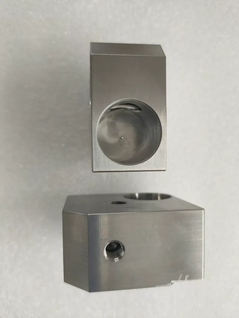
The housing carries a 1/4″-28 UNF 2B thread and an M8×1.25 thread, both with a chamfer cut to the root of the first thread. That chamfer must protect the first thread from damage without cutting into the effective thread form. Fine threads in 316L tear and burr easily, and the usual deburring pass is exactly what damages the thread profile.
R0.05 where the part is welded
The weld zone is specified at R0.05 max, with no burrs and no dents. It is a weld preparation face: a radius that grows changes the groove, the fusion and the seal. It may not be polished, and it cannot be reached with a general deburring tool, so the edge has to be made correctly at the machine.
Burrs hidden inside intersecting holes
The side holes break into the main bore, and the burr forms on the inside, where it cannot be seen or reached with a file. Manual deburring through the bore scratches the Ra 0.8 wall; leaving the burr risks a loose fragment in the assembly. Both failures are discovered late, which makes the deburring method a process decision rather than a finishing detail.
Thin walls and a regulated product
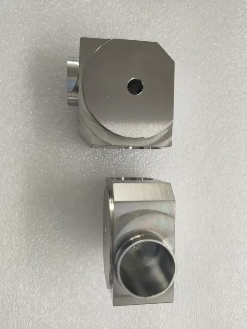
The main bore wall is thin, and 316L generates enough cutting heat to distort it. Clamping too hard collapses it; cutting too fast shrinks the bore. Rough and finish have to be separated, with stress relief after roughing. On top of that, the part is an agency-approved product: material certificates, process records and shock-proof packaging are part of the specification, not extras.
Our Approach
- •Stainless-specific cutting data: sharp, coated tooling, high coolant volume and surface speeds kept below the work-hardening band.
- •One datum scheme carried through every setup, with the main bore established first and all subsequent faces located from it.
- •Rough and finish separated with stress relief, and low-pressure clamping on the thin wall, so the H8 bore is cut in a part that has stopped moving.
- •Threads milled or tapped with dedicated tooling, the root chamfer cut in the same operation, and no general deburring pass afterwards.
- •Controlled cross-hole deburring from the inside out, with the bore protected, so no burr remains and no scratch is left on the Ra 0.8 wall.
- •Weld edges produced at the machine to R0.05 max and checked before the part leaves the cell, rather than corrected by hand later.
- •Full documentation and protected packaging: material certificate, inspection records and shock-proof packing for an agency-approved part.
The Result
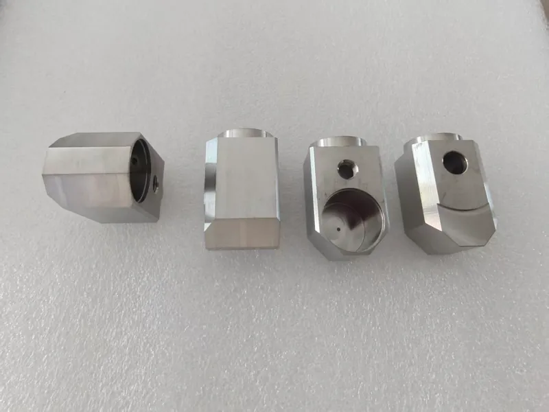
The housings were delivered with the H8 and H10 bores in tolerance, perpendicularity held to 0.01 mm, weld zones at R0.05 max, and Ra 0.8 across the machined faces. Threads passed their gauges with the root chamfers intact, and the batch shipped with the documentation and shock-proof packing the product approval requires.
Stainless sensor housing with a weld callout? Send the drawing and the assembly it seals into. We will review datums, bore strategy and the weld-edge preparation before the first operation is programmed.