
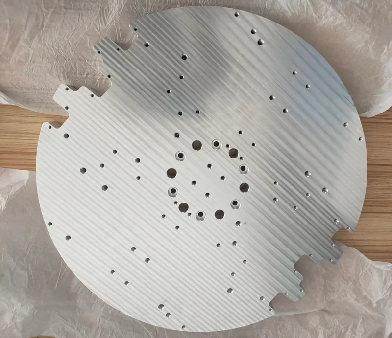
A large circular base plate looks simple in a 3D viewer and behaves nothing like it on a machine. This part — a 7075-T6 aluminum disc with dense precision hole groups and irregular notches around the outer edge — has to stay flat while most of its material is removed, and every hole has to land where the mating assembly expects it.
| Part | Large-diameter circular base plate |
|---|---|
| Material | 7075-T6 aviation aluminum plate |
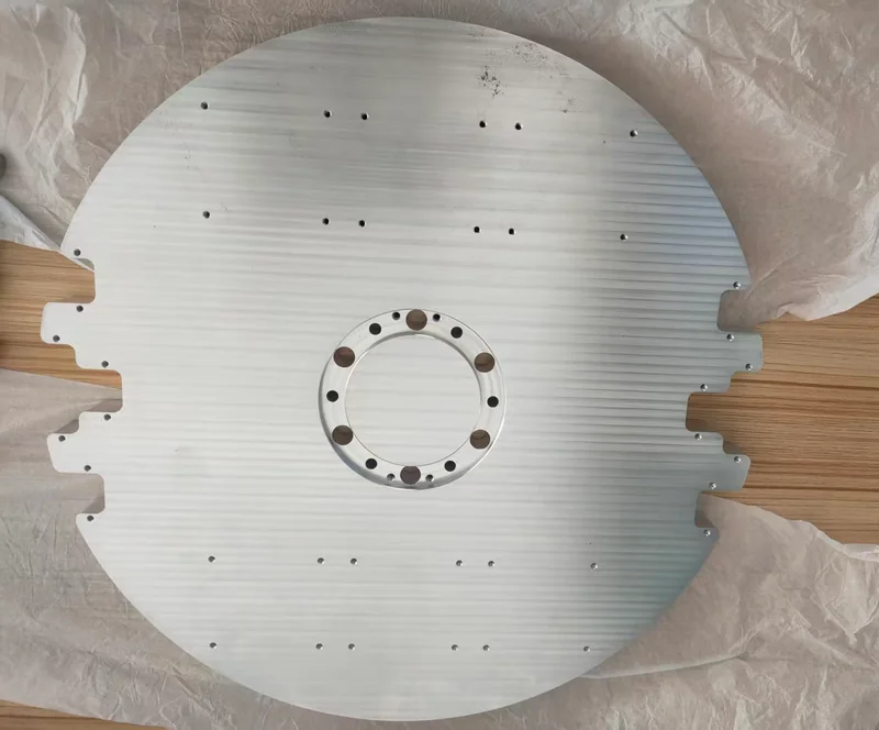
| Features | Precision hole groups, centre bore, irregular edge notches on both faces |
| Critical geometry | Parallelism, flatness and hole position |
| Edge treatment | Chamfer ≤ 0.1 mm, burr-free |
| Untoleranced dims | H12/h12 · ±IT12/2 |
The Challenge
Stress control on a mostly-empty disc
The plate starts as a thick 7075-T6 plate with high internal stress. By the time all the pockets, holes and notches are cut, a large share of that material is gone — and the balance of stress inside what remains changes as it goes. Without a disciplined sequence of rough machining plus stress-relief aging, the disc bows and the flatness callout fails no matter how accurately it was machined.
Two-sided precision work
Both faces carry precision position holes, a centre bore and irregular clamping slots. That means flipping the part multiple times — and every flip risks clamping distortion on a large, thin section. Parallelism and flatness must survive all of it, and edge chamfers must stay within 0.1 mm with no burrs, because the edges act as assembly reference surfaces.
Hole groups that decide whether the machine assembles
The dense hole pattern is a positioning interface. A small deviation in a single hole group shifts the whole assembly, so all holes are inspected before shipment rather than sampled. Surface areas that were specifically called out must also be free of tool marks and burrs.
Fixturing without crushing the disc
A large-diameter thin disc cannot be held with heavy clamps — the clamp load becomes the distortion. It needs flexible fixturing that supports the part across its area and holds it without bending it.
Our Approach
- •Rough machining with controlled allowance, followed by stress-relief aging before any finishing operation.
- •Flexible, distributed fixturing across the disc face so clamping force never becomes part geometry.
- •One datum scheme for every setup, so flipping the part does not introduce cumulative position error in the hole groups.
- •Deburring and chamfer control at ≤ 0.1 mm, verified by inspection rather than left to hand finishing.
- •100% hole inspection plus CMM verification of flatness and parallelism.
The Result
The plate shipped flat, with hole groups positioned for direct assembly and edges prepared as reference surfaces — the result of controlling stress and clamping rather than chasing the geometry at the end of the process.
Large plate or frame to machine? Send the model and the assembly it fits into. We will review flatness strategy, datum scheme and hole-position control before the first chip is cut.