
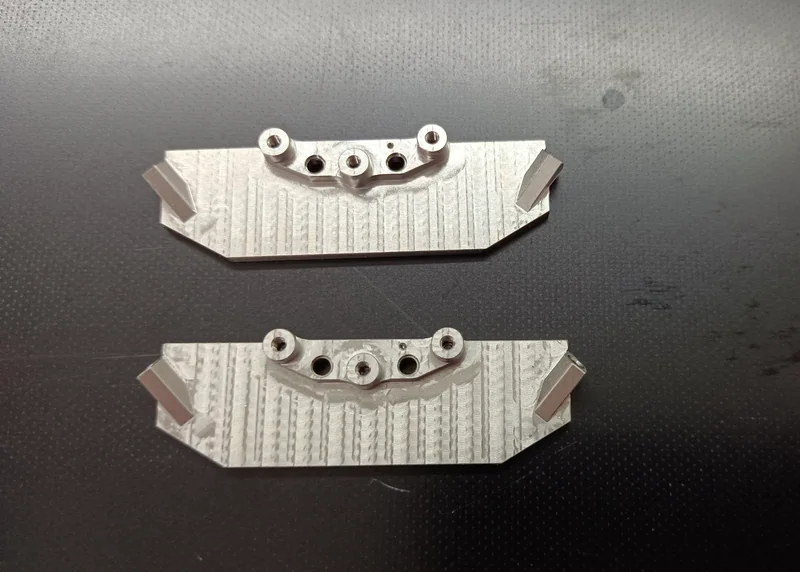
Thin-wall parts are where machining plans usually fall apart. A European customer ordered two stainless steel cover parts — prototype plus a 1,000-set production batch — with wall sections as thin as 0.8 mm. Holding them flat, on size and repeatable across a thousand pieces was the entire project.
| Parts | 2 stainless steel cover components (one part code F741134_067) |
|---|---|
| Volume | Prototype + 1,000 sets |
| Wall thickness | 0.8 mm minimum · ≤3 mm overall · wall-to-body ratio under 0.1 |
| Material | Stainless steel |
| Drawing tolerances | H14/h14 · ±IT14/2 on untoleranced dimensions |
| Result | Flat parts, all dimensions in specification, 1,000 sets delivered |
The Challenge
Cutting force turns into elastic deflection
When the wall is only 0.8 mm thick — or the wall-to-body ratio drops below 0.1 — the material simply moves away from the cutter. The tool pushes the wall back, the cut measures correctly while clamped, and then the part springs back the moment the clamps are released. Parts like this fail inspection even though they were “machined to size”.
Clamping marks and resonance
Two related problems, both caused by rigidity that simply is not there:
- ✓Point-contact hard clamping leaves visible dents on a thin stainless wall — the part is cosmetically rejected before anyone measures it.
- ✓Very low natural frequency. A thin wall resonates with the spindle and tool frequency, printing chatter marks across the surface and pushing roughness out of specification.
Residual stress moves the part after roughing
Stainless blanks carry internal stress from rolling and forming. When rough machining removes a large amount of material, that stress redistributes and the part twists on its own. Finishing passes cannot correct a distortion that appears after they are finished.
Tolerances and datums that do not match reality
The drawing specified H14/h14 and ±IT14/2 across the whole part. Held literally, that forces slower feed rates, extra finishing passes and 100% inspection — roughly doubling production cost — even though most of those dimensions do not touch function. At the same time, the drawing left the machining datum and the assembly datum as separate features, so every setup introduced cumulative error, and the irregular curved surfaces offered no obvious locating face for repeatable batches.
Our Approach
- •Stress relief before finishing so the blank stops moving before the final passes.
- •Flexible, distributed clamping instead of point contact — holding the part without printing the fixture into the surface.
- •Cutting strategy tuned for thin walls: reduced radial engagement, lighter passes and tool paths that keep force directed into the part instead of into the wall.
- •A single, agreed datum scheme carried through every operation, so hole positions and profiles stay consistent from setup to setup.
- •Inspection plan for the part: CMM inspection in accordance with the part drawing.
The Result
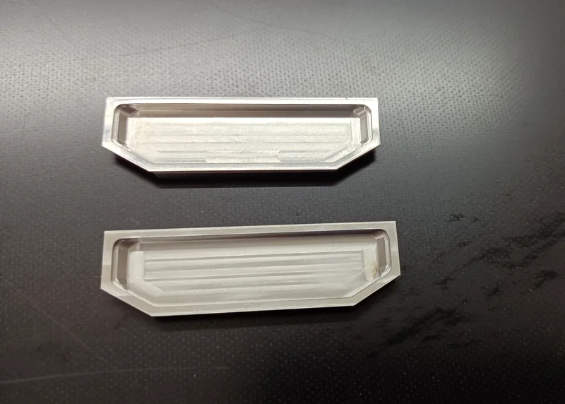
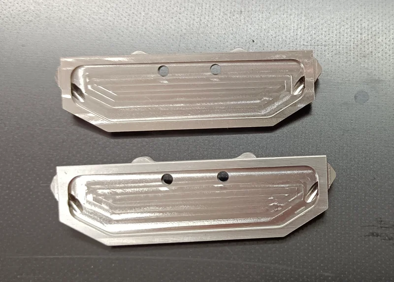
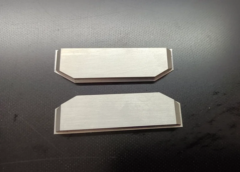
Both cover parts shipped flat and within specification across the full 1,000-set batch — with consistent geometry from the first set to the last, because the process was stabilised rather than the parts being reworked.
Thin-wall part in your drawing? Share the model and the annual volume — we will propose a clamping and cutting strategy, and tell you which tolerances are driving cost and which ones could be relaxed.