
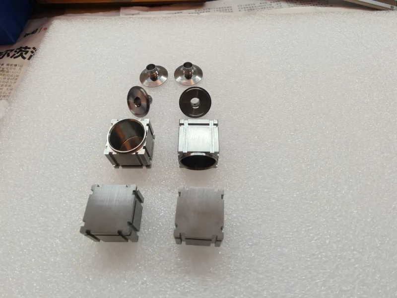
A thin-wall sensor housing machined from Ti-6Al-4V Grade 5 (3.7165), with four external locating claws, a Φ16.30 mm bore held to +0.07/−0.05 mm, and weld-zone edges capped at R0.05. The order is 250 pieces: small enough to be manageable, large enough that tool wear has to be watched.
| Part | 3-axis sensor housing, thin-wall cylinder with four external locating claws |
|---|---|
| Material | Ti-6Al-4V Grade 5 (3.7165) |
| Bore | Φ16.30 mm, +0.07/−0.05 mm (H10 per drawing) |
| Weld edges | R0.05 max, no burrs, no dents |
| Chamfers | C0.05–0.1 (0.10 × 45°), no over-break |
| Surface | Ra 1.6 on machined faces, burr-free |
| Tolerances | ISO 2768-fH on untoleranced dimensions |
| Documentation | MTC with heat number, chemistry and mechanical properties · 1–2 first-article samples |
The Challenge
Titanium moves away from the tool
Ti-6Al-4V conducts heat poorly, so the heat of cutting concentrates at the tool tip instead of disappearing into the part. The material also springs back and tends to gall against the cutting edge. The result is a narrow window: too aggressive and the bore is pushed out of tolerance, too light and the tool rubs. Carbide with a dedicated coating and controlled cooling is not optional here.
A precision bore in a thin wall
The Φ16.30 H10 bore sits in a thin sleeve. Clamping force, cutting stress and heat all show up as bore shrinkage or ovality, so the bore has to be roughed and finished in separate operations, with a stress-relief step between them and soft jaws or internal support for the finish. Grip it hard and the part measures correctly only while it is still in the chuck.
R0.05 at the weld joint
The weld-zone edge is specified at R0.05 max: no larger radius, no sharp corner, no burr and no dent. That edge is the weld preparation face: a radius that grows even slightly changes the groove and therefore the weld itself. Standard deburring and vibratory finishing remove material far too freely to be trusted near it.
Four claws that are easy to break
The locating claws are thin, protruding features on an irregular outline. They are the weakest part of the workpiece and the easiest to chip, deflect or break during machining and handling. The machining sequence has to protect them: cut the main body first, keep rigidity as long as possible, and finish the claws last.
Mass finishing without collateral damage
The drawing allows mass finishing, which is the practical way to deburr a batch of 250. But the same process that removes a burr can round the R0.05 weld edge, enlarge the C0.05–0.1 chamfers and dull the bore. The finishing media, time and part orientation have to be proven on samples before the batch goes through.
Tool wear across 250 pieces
Titanium wears tools predictably but steadily. Bore size, weld-edge radius and chamfer width all drift in the same direction as the edge breaks down, so the process needs scheduled checks and planned tool changes rather than a single setup at the start of the run.
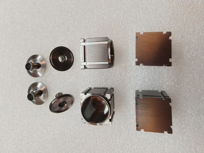
Our Approach
- •Titanium-specific cutting strategy: coated carbide, sharp edges, high-pressure coolant and conservative surface speed to keep heat out of the part and stop galling.
- •Rough and finish separated with stress relief between, so the bore stops moving before the H10 finishing passes are cut.
- •Soft jaws and internal support for the thin sleeve: the part is located, not squeezed, and clamping force is kept low and repeatable.
- •Sequence built around rigidity: main body first, claws last, with the part supported while the thin features are machined.
- •Edge control by tooling, not by hand: the R0.05 weld edge and C0.05–0.1 chamfers are produced with controlled tools, and mass finishing is validated on first articles before it touches the batch.
- •Scheduled in-process checks of bore size, weld-edge radius and chamfer width as tools wear, with planned tool changes instead of reactive ones.
- •Traceability from the mill certificate, with 1–2 samples sent for first-article approval before the 250-piece run.
The Result
The housings held the H10 bore without ovality, kept the weld edges at R0.05 max and the chamfers inside C0.05–0.1, and were delivered with full MTC traceability. First-article samples were approved before the batch ran, so the edge and surface condition were agreed before production rather than argued over at delivery.
Thin-wall titanium housing in your design? Send the drawing and the weld preparation detail. Our engineers will review bore strategy, clamping and edge control before quoting, because those three decide the cost of the part.